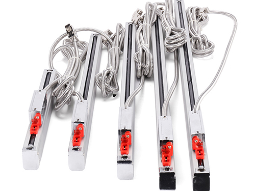
Electronic Ruler, Milling Machine Electronic Ruler, Digital Display Electronic Ruler
Electronic Ruler, Milling Machine Electronic Ruler, Digital Display Electronic Ruler
The installation of grating ruler linear displacement sensor is more flexible and can be installed in different parts of the machine tool.
Generally, the main ruler is installed on the worktable (sliding board) of the machine tool, and the bed moves with the knife. The reading head is fixed on the bed, and the reading head should be installed below the main ruler as much as possible. The choice of the installation method must pay attention to the direction of the chips, cutting fluid and oil splashing. If it is necessary to install with the reading head facing upward due to the limitation of the installation position, an auxiliary sealing device must be added. In addition, under normal circumstances, the reading head should be installed as far as possible on the stationary part of the machine tool. At this time, the output wire should not move and easy to fix, while the ruler body should be installed on the part that moves relative to the machine tool (such as a skateboard).
1. Mounting base of linear displacement sensor of grating ruler
When installing the grating ruler sensor, the sensor cannot be directly installed on a rough and uneven machine tool, let alone a primed machine tool. The grating main ruler and the reading head are respectively installed on two parts of the machine tool that move relative to each other. Use a dial indicator to check the parallelism between the main ruler installation surface of the machine tool table and the direction of the guide rail movement. The dial indicator is fixed on the bed, and the mobile workbench is required to achieve a parallelism within 0.1mm/1000mm. If this requirement cannot be met, a grating ruler base needs to be designed and processed.
The requirements of the base: (1) A base equal to the length of the grating ruler should be added (preferably, the base should be about 50mm longer than the grating ruler). (2) The base is processed through milling and grinding procedures to ensure that its plane parallelism is within 0.1mm/1000mm. In addition, it is necessary to process a reading head base with the same height as the ruler base. The total error between the base of the reading head and the base of the ruler shall not exceed ±0.2mm. When installing, adjust the position of the reading head so that the parallelism between the reading head and the grating ruler body is about 0.1mm, and the distance between the reading head and the grating ruler body is about 1~1.5mm.

2. Installation of main ruler of linear displacement sensor of grating ruler
Use M4 screws to mount the grating main ruler on the installation surface of the workbench where the machine tool is installed, but do not tighten it, fix the dial gauge on the bed, and move the workbench (the main ruler and the workbench move at the same time). Use a dial gauge to measure the parallelism between the plane of the main ruler and the direction of movement of the machine tool rail, adjust the position of the main ruler M4 screw, and tighten the M2 screw completely when the main ruler parallelism is within 0.1mm/1000mm.
When installing the grating ruler, you should pay attention to the following three points:
(1) When installing the main ruler, such as installing a grating larger than 1.5M, it is not possible to install only the two ends like a bridge type. Support is still required in the entire main ruler body. (2) After installation with a base, it is best to use a clip to clamp the midpoint (or several points) of the ruler body. (3) When the clip cannot be installed, it is best to stick the grating ruler body with glass glue to fix the base ruler and the main ruler.
3. Installation of reading head of grating ruler linear displacement sensor
When installing the reading head, first ensure that the base surface of the reading head meets the installation requirements, and then install the reading head. The installation method is similar to that of the main ruler. Finally, adjust the reading head to ensure that the parallelism between the reading head and the main scale of the grating is within 0.1mm, and the gap between the reading head and the main scale is controlled within 1~1.5mm.
4. Limiting device for linear displacement sensor of grating ruler
After all the grating linear displacement sensors are installed, a limit device must be installed on the machine tool rail to prevent the reading head from colliding with the two ends of the main ruler when the machine tool is moving, thereby damaging the grating ruler. In addition, when purchasing a grating linear displacement sensor, the user should try to choose a grating ruler that exceeds the machining size of the machine by about 100mm to leave a margin.
5. Inspection of linear displacement sensor of grating ruler
After the grating line displacement sensor is installed, you can turn on the digital display meter, move the workbench, and observe whether the digital display meter counts normally.
Select a reference position on the machine tool, and move the work point back and forth to the selected position. The readings of the digital display should be the same (or return to zero). In addition, you can also use a dial indicator (or dial indicator) to adjust the dial indicator and digital indicator to zero at the same time (or remember the initial data), return to the initial position after several rounds, and observe the digital indicator and the indicator. Whether the data in the table is consistent.
Through the above work, the installation of the linear displacement sensor of the grating ruler is completed. But for the general machine tool processing environment, there are more iron filings, cutting fluid and oil stains. Therefore, the sensor should be equipped with a protective cover. The design of the protective cover is determined according to the size of the sensor's cross-section enlargement and leaving a certain space. The protective cover is usually sealed with rubber to make it have a certain degree of water and oil resistance.
About
Introduction Plant ApplicationProduct
Grating Ruler Digital Display Magnetic Scale Series Ball Grid SeriesNews
Company Dynamics Industry Information Common ProblemConnect
Recruitment Phone Addresstel:+86 186-8881-1140
Address:Room 702, Building 1, No. 23, Wusha Xing 4th Road, Chang'an Town, Dongguan City, Guangdong Province
tel:+86 0769-81667321
Dongguan Jiewei Electronic Technology Co., Ltd. Copyright © 2021 All Rights Reserved